- 您现在的位置:买卖IC网 > Sheet目录17376 > ISL60002DIH310Z-T7A (Intersil)IC VREF SERIES PREC SOT-23-3
ISL60002
Board Assembly Considerations
FGA references provide high accuracy and low temperature drift
but some PC board assembly precautions are necessary. Normal
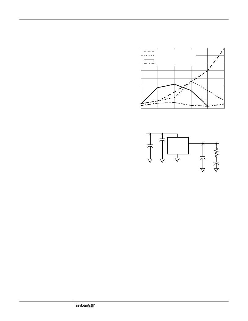
Output voltage shifts of 100μV to 1mV can be expected with
significantly over the full bandwidth. As shown in Figure 118,
noise is reduced to less than 40μV P-P from 1Hz to 1MHz using
this network with a 0.01μF capacitor and a 2k Ω resistor in series
with a 10μF capacitor.
Pb-free reflow profiles. Precautions should be taken to avoid
excessive heat or extended exposure to high reflow
temperatures, which may reduce device initial accuracy.
Post-assembly x-ray inspection may also lead to permanent
changes in device output voltage and should be minimized or
avoided. If x-ray inspection is required, it is advisable to monitor
the reference output voltage to verify excessive shift has not
occurred. If large amounts of shift are observed, it is best to add
an X-ray shield consisting of thin zinc (300μm) sheeting to allow
clear imaging, yet block x-ray energy that affects the FGA
reference.
Special Applications Considerations
400
350
300
250
200
150
100
50
CL = 0
CL = 0.001μF
CL = 0.1μF
CL = 0.01μF AND 10μF + 2k Ω
In addition to post-assembly examination, there are also other
X-ray sources that may affect the FGA reference long term
0
1
10
100
1k
10k
100k
accuracy. Airport screening machines contain X-rays and will
have a cumulative effect on the voltage reference output
accuracy. Carry-on luggage screening uses low level X-rays and is
not a major source of output voltage shift, however, if a product is
expected to pass through that type of screening over 100 times,
V IN = 3.0V
FIGURE 118. NOISE REDUCTION
it may need to consider shielding with copper or aluminum.
Checked luggage X-rays are higher intensity and can cause
output voltage shift in much fewer passes, thus devices expected
to go through those machines should definitely consider
shielding. Note that just two layers of 1/2 ounce copper planes
will reduce the received dose by over 90%. The leadframe for the
device which is on the bottom also provides similar shielding.
0.1μF
10μF
V IN
V O
ISL60002-25
VOUT = 2.50V
GND
0.01μF
2k Ω
10μF
If a device is expected to pass through luggage X-ray machines
numerous times, it is advised to mount a 2-layer (minimum) PC
board on the top, and along with a ground plane underneath will
effectively shield it from 50 to 100 passes through the machine.
Since these machines vary in X-ray dose delivered, it is difficult to
produce an accurate maximum pass recommendation.
Noise Performance and Reduction
The output noise voltage in a 0.1Hz to 10Hz bandwidth is
typically 30μV P-P . This is shown in the plot in the Typical
Performance Curves. The noise measurement is made with a
bandpass filter made of a 1 pole high-pass filter with a corner
frequency at 0.1Hz and a 2-pole low-pass filter with a corner
frequency at 12.6Hz to create a filter with a 9.9Hz bandwidth.
Noise in the 10kHz to 1MHz bandwidth is approximately
400μV P-P with no capacitance on the output, as shown in
Figure 118. These noise measurements are made with a 2
decade bandpass filter made of a 1 pole high-pass filter with a
corner frequency at 1/10 of the center frequency and 1-pole
low-pass filter with a corner frequency at 10 times the center
frequency. Figure 118 also shows the noise in the 10kHz to 1MHz
band can be reduced to about 50μV P-P using a 0.001μF
capacitor on the output. Noise in the 1kHz to 100kHz band can
be further reduced using a 0.1μF capacitor on the output, but
noise in the 1Hz to 100Hz band increases due to instability of the
very low power amplifier with a 0.1μF capacitance load. For load
capacitances above 0.001μF the noise reduction network shown
in Figure 119 is recommended. This network reduces noise
35
FIGURE 119. NOISE REDUCTION NETWORK
Turn-On Time
The ISL60002 devices have ultra-low supply current and thus the
time to bias up internal circuitry to final values will be longer than
with higher power references. Normal turn-on time is typically
7ms. This is shown in Figure 120. Since devices can vary in
supply current down to >300nA, turn-on time can last up to about
12ms. Care should be taken in system design to include this
delay before measurements or conversions are started.
FN8082.19
January 16, 2014
发布紧急采购,3分钟左右您将得到回复。
相关PDF资料
594D475X9020B8T
CAP TANT 4.7UF 20V 10% 1611
R1S-0524/H-R
CONV DC/DC 1W 05VIN 24VOUT
594D685X9020B8T
CAP TANT 6.8UF 20V 10% 1611
R1S-0515/H-R
CONV DC/DC 1W 05VIN 15VOUT
R1S-0509/H-R
CONV DC/DC 1W 05VIN 09VOUT
594D226X96R3B8T
CAP TANT 22UF 6.3V 10% 1611
R1S-0505/H-R
CONV DC/DC 1W 05VIN 05VOUT
594D156X9016B8T
CAP TANT 15UF 16V 10% 1611
相关代理商/技术参数
ISL60002DIH310Z-TK
功能描述:基准电压& 基准电流 PREC 1.024V LW VOLT FGA REF 5.0MV -40TO RoHS:否 制造商:STMicroelectronics 产品:Voltage References 拓扑结构:Shunt References 参考类型:Programmable 输出电压:1.24 V to 18 V 初始准确度:0.25 % 平均温度系数(典型值):100 PPM / C 串联 VREF - 输入电压(最大值): 串联 VREF - 输入电压(最小值): 分流电流(最大值):60 mA 最大工作温度:+ 125 C 封装 / 箱体:SOT-23-3L 封装:Reel
ISL60002DIH311Z
制造商:Rochester Electronics LLC 功能描述: 制造商:Intersil Corporation 功能描述:
ISL60002DIH311Z-TK
功能描述:基准电压& 基准电流 PBFREE PRECISION 1 20V LW V FGAF 5 0MV RoHS:否 制造商:STMicroelectronics 产品:Voltage References 拓扑结构:Shunt References 参考类型:Programmable 输出电压:1.24 V to 18 V 初始准确度:0.25 % 平均温度系数(典型值):100 PPM / C 串联 VREF - 输入电压(最大值): 串联 VREF - 输入电压(最小值): 分流电流(最大值):60 mA 最大工作温度:+ 125 C 封装 / 箱体:SOT-23-3L 封装:Reel
ISL60002DIH312
制造商:INTERSIL 制造商全称:Intersil Corporation 功能描述:Precision 1.25V & 2.50V Low Voltage FGA References
ISL60002DIH312-TK
功能描述:IC VREF SERIES PREC SOT-23-3 RoHS:否 类别:集成电路 (IC) >> PMIC - 电压基准 系列:FGA™ 标准包装:3,000 系列:- 基准类型:旁路,精度 输出电压:5V 容差:±0.5% 温度系数:100ppm/°C 输入电压:- 通道数:1 电流 - 阴极:80µA 电流 - 静态:- 电流 - 输出:15mA 工作温度:-40°C ~ 85°C 安装类型:表面贴装 封装/外壳:TO-236-3,SC-59,SOT-23-3 供应商设备封装:SOT-23-3 包装:带卷 (TR) 其它名称:LM4040CIM3-5.0MLTRLM4040CIM3-5.0MLTR-ND
ISL60002DIH312Z
制造商:Intersil Corporation 功能描述:REF 1.25V LOW POWER FGA SOT-23-3 制造商:Intersil Corporation 功能描述:REF 1.25V LOW POWER FGA, SOT-23-3 制造商:Intersil Corporation 功能描述:REF 1.25V LOW POWER FGA, SOT-23-3; Topology:Series; Input Voltage:2.7V to 5.5V; Reference Voltage:1.25V; Reference Voltage Tolerance:5mV; Voltage Reference Case Style:SOT-23; No. of Pins:3; Temperature Coefficient:20ppm/C; Operating;RoHS Compliant: Yes 制造商:Intersil Corporation 功能描述:REF 1.25V LOW POWER FGA, SOT-23-3; Topology:Series; Input Voltage Min:2.7V; Input Voltage Max:5.5V; Reference Voltage:1.25V; Reference Voltage Tolerance:5mV; Voltage Reference Case Style:SOT-23; No. of Pins:3; Temperature ;RoHS Compliant: Yes
ISL60002DIH312Z-T7A
功能描述:基准电压& 基准电流 PREC 1.25V LW VOLT FGA REF 5.0MV -40TO RoHS:否 制造商:STMicroelectronics 产品:Voltage References 拓扑结构:Shunt References 参考类型:Programmable 输出电压:1.24 V to 18 V 初始准确度:0.25 % 平均温度系数(典型值):100 PPM / C 串联 VREF - 输入电压(最大值): 串联 VREF - 输入电压(最小值): 分流电流(最大值):60 mA 最大工作温度:+ 125 C 封装 / 箱体:SOT-23-3L 封装:Reel
ISL60002DIH312Z-TK
功能描述:IC VREF SERIES PREC SOT-23-3 RoHS:是 类别:集成电路 (IC) >> PMIC - 电压基准 系列:FGA™ 标准包装:1 系列:- 基准类型:旁路,可调节,精度 输出电压:2.495 V ~ 36 V 容差:±1% 温度系数:标准值 34ppm/°C 输入电压:2.495 V ~ 36 V 通道数:1 电流 - 阴极:1mA 电流 - 静态:- 电流 - 输出:100mA 工作温度:-40°C ~ 85°C 安装类型:表面贴装 封装/外壳:TO-236-3,SC-59,SOT-23-3 供应商设备封装:SOT-23-3 包装:剪切带 (CT) 产品目录页面:1073 (CN2011-ZH PDF) 其它名称:296-17329-1